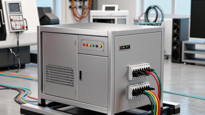
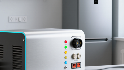
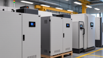
Choosing an Automatic Step Up Stabilizer is not simply a matter of selecting the highest voltage rating. It requires a clear understanding of incoming voltage, connected equipment, load behavior, and installation conditions. A stabilizer that performs well in a quiet office may struggle in a workshop with motor starts, welding equipment, or long cable runs. Small details matter.
Power-quality specialist Dr. Math H. J. Bollen states, “Power quality is the combination of voltage quality and current quality.” This principle guides a practical selection process. Buyers should examine input-voltage variation, output accuracy, response time, rated capacity, phase configuration, and protection functions. Thermal performance also deserves attention. A unit operating beside a furnace needs more careful evaluation than one installed in a cool electrical room.
Field experience shows that confusing kVA with actual load demand causes avoidable problems. So does ignoring starting current. A pump may draw far more power for several seconds than its nameplate suggests. That moment can trip protection or weaken output voltage. No selection method is perfect. Specifications may look convincing, yet real conditions can expose hidden weaknesses. Measurements are better than assumptions.
This guide explains how to compare an Automatic Step Up Stabilizer using practical electrical data and manufacturer evidence. It also considers efficiency, maintenance access, noise, installation space, and long-term reliability. Readers will learn which questions to ask before purchasing. They will also see why the cheapest option is not always the safest value. Sometimes, the overlooked detail decides everything.
An automatic step-up stabilizer raises low input voltage and keeps the output near a safer, usable level. It senses voltage changes continuously. Then, a transformer or electronic circuit adjusts the output automatically. Voltage can wander. This often happens in rural lines, workshops, or buildings with heavy starting loads. Lights may flicker, motors may hum, and sensitive equipment can restart unexpectedly. The stabilizer helps reduce these fluctuations, but it cannot repair damaged wiring or create unlimited power.
Choosing one requires more than matching the appliance wattage. Check the lowest and highest incoming voltage, then compare them with the stabilizer’s operating range. Select the correct output voltage and allow extra capacity for motor-starting currents. A refrigerator, pump, or compressor may briefly demand several times its running power. Small details matter. Look for overload protection, thermal protection, clear meters, proper grounding, and a response time suited to the equipment. A qualified electrician should verify the connection and ventilation space. In practical installations, users often focus on capacity and overlook heat buildup. That mistake can shorten service life. I would also question any specification that lacks testing conditions, because “stable output” can mean very different things in real homes and workshops.
Choosing an automatic step up stabilizer starts with the voltage, not the cabinet size. Measure the lowest and highest input voltage at the equipment’s connection point. A short reading is not enough. Record measurements during busy operating hours, when supply voltage often changes.
The stabilizer’s output must match the equipment requirement, such as 220 or 230 volts, with the correct frequency and phase. Check the total running load in watts or volt-amperes. Motors, compressors, and transformers may draw several times their normal current during startup.
Do not guess. Review the equipment nameplate and, when possible, use a clamp meter during startup. Select capacity with practical headroom, often 20 to 30 percent above the measured continuous load. More may be needed for heavy inductive equipment.
Equipment requirements also include response speed, output accuracy, cooling, and protection features. Sensitive control systems may need tighter voltage regulation than heaters or basic lighting.
Look for overload protection, short-circuit protection, surge handling, and a safe bypass function. Confirm that the installation supports the stabilizer’s cable size, grounding method, and ventilation clearance.
A qualified electrical professional should verify these points before connection. In real installations, space and heat are easily underestimated. That mistake can reduce service life, even when the capacity calculation appears correct.
An automatic step up stabilizer raises low input voltage and keeps equipment within a safer operating range. Relay-type stabilizers switch between preset voltage steps. They are affordable and suitable for basic appliances, but their output may fluctuate slightly. Servo-controlled models adjust voltage through a motorized mechanism. They usually provide better accuracy, although the motor can respond slowly and requires maintenance. Static stabilizers use electronic components, offering rapid correction and silent operation. Their higher cost may not suit every installation.
Control systems deserve close attention. A reliable unit should measure true RMS voltage, not only approximate waveform levels. Microprocessor control can improve accuracy and record faults. Check response time, adjustment range, display clarity, and remote monitoring options. A stabilizer that corrects voltage quickly may still perform poorly if its sensing range is too narrow. This is easy to miss. Load type matters too, because motors and compressors often create short starting surges.
Tips: Match the stabilizer capacity to the real load, then allow 20–30% spare capacity. Look for overload, short-circuit, overheat, and high-voltage protection. A time-delay function helps protect compressors after an outage. Surge protection and a manual bypass can improve service safety. During inspection, leave ventilation space around the cabinet and check terminal tightness. Protection features sound convincing, but their actual ratings and test conditions need verification. I would not choose from a feature list alone. Measure the site voltage across several hours, especially during peak demand.
Choosing an automatic step-up stabilizer starts with the installation environment, not the product label. Record the lowest and highest incoming voltage during working hours. Check phase balance, frequency, grounding, ambient temperature, dust, and available ventilation. The stabilizer must handle the connected kVA and short-term inrush from motors, pumps, or compressors. IEC 60038 provides reference voltage values, while IEC 61000-4-30 defines methods for measuring power quality. A site survey using these principles is more reliable than one handheld reading.
Efficiency deserves equal attention. The IEA’s Electricity 2024 report states that data centres used about 460 TWh globally in 2022, with demand potentially exceeding 1,000 TWh by 2026. Small conversion losses therefore become expensive in continuous operations. Request efficiency figures at 25%, 50%, and 100% load, rather than one attractive headline number. Measure input and output power after installation. Heat tells a story. A stabilizer operating near its limit may waste energy and shorten component life. A spreadsheet can still miss poor ventilation.
Maintenance needs should be visible before purchase. Confirm access for cleaning, terminal tightening, fan replacement, alarm testing, and bypass inspection. The U.S. Department of Energy notes that motor systems can represent a major share of industrial electricity use, making voltage stability important for heavily loaded equipment. Schedule thermal scanning and voltage logging at practical intervals. Field conditions are rarely perfect. Dust accumulates faster than planned, and load patterns change. Leave capacity margin, keep service records, and review the settings after major equipment is added.
| Assessment Area | Installation Condition or Requirement | Reference Data or Typical Range | Selection Guidance | Maintenance Impact | Priority |
|---|---|---|---|---|---|
| Input Voltage | Measure the lowest and highest voltage at the installation point during normal operating hours. | Record the actual range; a common low-voltage application may require input coverage such as 140–260 V for a 220–240 V system. | Choose an input range that covers the measured minimum and maximum voltage with additional operating margin. | Recheck voltage after major changes to the utility supply or connected load. | Critical |
| Output Voltage | Confirm the rated voltage required by the connected equipment. | 220–240 V AC is common for single-phase equipment; three-phase systems may use 380–415 V line-to-line. | Match the stabilizer output voltage, phase configuration, and frequency to the load requirements. | Verify output voltage during scheduled inspections and after repair work. | Critical |
| Load Capacity | Calculate the total running load and identify motors, compressors, pumps, or transformers that create starting current. | For continuous operation, select at least 20–30% capacity margin above the calculated load. Motor starting current can be several times the rated running current. | Size by apparent power in VA or kVA, not only by watts. Consider the largest starting load separately. | Overloading causes heat buildup, nuisance trips, and shortened component life. | Critical |
| Power Factor | Review the power factor of inductive or electronic loads. | Many commercial loads operate around 0.7–0.95 power factor, depending on equipment type and correction systems. | Use the manufacturer’s kVA rating and avoid converting watts to VA with an assumed power factor that is too high. | Unexpectedly low power factor may increase current and operating temperature. | Check |
| Efficiency | Compare energy losses at the expected operating load rather than only at full load. | Well-designed automatic stabilizers commonly achieve approximately 95–99% efficiency, depending on technology, input condition, and load. | Prefer higher efficiency when the stabilizer operates continuously or serves a high-load installation. | Keep ventilation openings clean because restricted airflow increases thermal losses. | Recommended |
| Response and Regulation | Determine how quickly the output must recover from input fluctuations. | Typical automatic units may regulate output within approximately one to several cycles, while motor-driven designs may respond more slowly than electronic designs. | Use faster regulation for sensitive control systems, laboratory equipment, and automation loads. | Inspect control sensors, switching devices, and moving mechanisms according to the service schedule. | Check |
| Frequency Compatibility | Confirm compatibility with the local electrical supply and the connected equipment. | Common operating frequencies are 50 Hz or 60 Hz; a voltage stabilizer normally does not correct frequency unless specifically designed to do so. | Do not use voltage stabilization as a substitute for a frequency converter or uninterruptible power supply. | Frequency should be checked when equipment shows abnormal motor or timing behavior. | Critical |
| Installation Location | Provide a dry, clean, well-ventilated area with sufficient clearance for heat dissipation and servicing. | Maintain the clearance specified by the equipment documentation; avoid direct sunlight, water exposure, conductive dust, and corrosive fumes. | Wall-mounted or floor-mounted construction should match the available space, cable routing, and load access. | Clean air inlets, outlets, and internal surfaces during routine service. | Critical |
| Ambient Conditions | Check temperature, humidity, altitude, and dust levels at the installation site. | Many standard electrical units are designed for approximately 0–40°C and non-condensing humidity; derating may be required at higher altitude or temperature. | Select an enclosure and derating level suitable for the actual environment. | Harsh environments require more frequent cleaning, inspection, and corrosion checks. | Check |
| Protection Functions | Identify risks from overload, short circuit, overvoltage, undervoltage, overheating, and phase loss. | Recommended protections include overload, overtemperature, output overvoltage, input undervoltage, and bypass or trip protection. | Choose protection functions based on the criticality and restart behavior of the connected equipment. | Test alarms, trips, breakers, and bypass operation during planned maintenance. | Critical |
| Grounding and Wiring | Use correctly sized conductors, protective devices, and a reliable protective earth connection. | Conductor and breaker ratings must comply with applicable electrical codes and the stabilizer’s rated current. | Installation should be performed by a qualified electrical professional; never remove the protective earth connection. | Inspect terminals for looseness, discoloration, corrosion, and heat damage. | Critical |
| Bypass Function | Determine whether the load must remain energized during stabilizer service or failure. | A maintenance bypass can allow the load to be supplied directly while the stabilizer is isolated, if the system is designed for safe bypass operation. | Choose a bypass arrangement with clear interlocking and safe transfer procedures. | Operate and inspect the bypass periodically; improper switching can expose equipment to unstable voltage. | Recommended |
| Noise and Location Sensitivity | Consider audible noise and electromagnetic compatibility near offices, medical areas, or measurement equipment. | Motorized units may produce audible mechanical noise during voltage correction; electronic units may generate switching noise if not properly filtered. | Place the unit away from quiet workspaces and sensitive signal wiring, or select a suitable low-noise design. | Inspect fans, relays, brushes, and mechanical drive components for unusual noise or vibration. | Check |
| Maintenance Schedule | Set inspection frequency according to operating hours, environment, and load criticality. | Visual inspection every 1–3 months and detailed electrical inspection at least annually are common starting points; harsh sites may require shorter intervals. | Follow the equipment documentation and local safety regulations rather than relying on a fixed interval alone. | Record input/output voltage, temperature, alarms, current, and inspection results for trend analysis. | Recommended |
| Technology Selection | Match the stabilizer design to the required response speed, accuracy, load type, and service conditions. | Servo-controlled designs provide continuous correction; relay-switched designs are generally simpler; electronic designs can offer fast response but may require stronger compatibility checks. | Prioritize regulation accuracy and response speed for sensitive loads; prioritize simplicity and serviceability for conventional loads. | Maintenance needs vary: mechanical systems require moving-part inspection, while electronic systems require thermal and connection checks. | Check |
| Total Cost of Ownership | Evaluate purchase cost, energy losses, installation, service, replacement parts, and downtime risk. | A small efficiency difference can become significant when the stabilizer operates continuously at a high load. | Select the unit with the best balance of capacity margin, efficiency, protection, serviceability, and expected operating life. | Maintain service records and replace worn components before they cause unplanned shutdowns. | Recommended |

How to Choose an Automatic Step Up Stabilizer?
Selecting a reliable model starts with the load, not the lowest quotation. Record the equipment’s rated voltage, running watts, and starting current. Motors and compressors may briefly draw three times their running current. A stabilizer sized only for normal watts can trip during startup. Leave at least 20% capacity headroom. More is safer, but not always economical.
Check the input range carefully. IEC 60038 defines preferred low-voltage system ranges, yet local supply conditions can differ sharply. In a rural workshop, a nominal 220-volt line may fall below 180 volts during evening demand. The International Energy Agency’s Electricity 2024 report forecasts global electricity demand growth of about 3.4% annually through 2026. Rising demand may increase local voltage stress. That does not automatically justify buying the largest unit.
Budget for lifetime cost. The U.S. Department of Energy estimates transformer losses consume roughly 2% of national electricity use, showing why efficiency deserves attention. Compare no-load consumption, correction speed, thermal protection, bypass operation, and serviceable parts. A slightly costlier model may repay the difference through lower losses and fewer failures. However, marketing efficiency figures can be difficult to verify. Ask for test conditions and certification records.
Installation matters too. Use a qualified electrician, proper earthing, and surge protection where needed. Keep ventilation clear; a dusty cabinet beside a hot wall is a poor arrangement. The cheapest option may work. It may also become an expensive lesson.