What Is a Marine Isolation Transformer and Why Use One?
A Marine Isolation Transformer is a quiet, unseen barrier between a vessel and shore power. It transfers electrical energy through magnetic induction, without creating a direct conductive connection. That separation can reduce galvanic corrosion, protect underwater metals, and improve electrical safety when the vessel is connected to a marina supply. Think of it as a controlled gate. Shore power enters. The boat’s onboard system receives power.
Marine electrician and author Nigel Calder explains the purpose in practical terms: “An isolation transformer separates the boat’s electrical system from the shore power system.” This principle matters near a wet dock, where a damaged cable, poor marina grounding, or small voltage difference can create serious corrosion. Bronze propellers, shaft seals, and through-hull fittings may show the evidence first. Sometimes, the damage remains hidden for months.
Choosing a Marine Isolation Transformer requires more than checking voltage and wattage. Installation quality matters. Cable sizing, overcurrent protection, ventilation, bonding, and monitoring must match the vessel’s design and applicable marine standards. A transformer is not a magic shield. It cannot correct every wiring mistake. It may also add weight, heat, noise, and cost. That trade-off deserves honest attention.
This guide examines how marine isolation transformers work, where they provide real value, and which limitations deserve careful review. The best decision depends on the vessel, shore supply, corrosion history, and electrical architecture. Small details matter. So does professional inspection.
Marine Isolation Transformers: 1:1 Voltage Ratio and 50/60 Hz Operation
A marine isolation transformer separates shore power from a vessel’s onboard electrical system. Its 1:1 voltage ratio keeps the nominal voltage unchanged. A 230-volt input produces approximately 230 volts at the output. However, copper losses and voltage drop remain. The label is not a guarantee of identical performance under every load.
Frequency is not converted. A transformer designed for 50/60 Hz can operate at either frequency when specified correctly. The output follows the input: 50 Hz in gives 50 Hz out, while 60 Hz in gives 60 Hz out. IEC 60092 guidance emphasizes suitable marine construction, insulation, temperature rise, and protection. Installers should verify voltage, frequency, VA capacity, short-circuit behavior, and enclosure conditions before connection.
Galvanic isolation can interrupt unwanted current paths between shore earth and the hull. That may reduce corrosion risk, nuisance tripping, and voltage differences around metal fittings. The transformer does not replace protective bonding or residual-current protection. It cannot correct poor wiring. According to UNCTAD’s Review of Maritime Transport 2023, more than 80% of global merchandise trade by volume moves by sea, increasing attention on dependable port-side electrical interfaces. DNV’s Maritime Forecast to 2050 also identifies shore power as an important efficiency measure for vessels in port. In practice, a warm transformer cabinet, audible hum, or unexpected voltage sag deserves investigation. Small details matter. A 1:1 specification is only the starting point.
How Galvanic Isolation Stops Shore-Power Leakage and Corrosion Currents
A marine isolation transformer separates a vessel’s AC system from shore power through magnetic induction. No direct conductive path connects the shore conductors to the boat’s onboard conductors. That separation is the key.
A small distinction matters. Galvanic corrosion usually begins when connected underwater metals experience small DC currents through bonding paths, shore protective earth, or nearby vessels. In a marina, these currents can move through the grounding system, propeller shafts, through-hulls, and seawater. The transformer interrupts the shore-side galvanic circuit, reducing one important route for corrosion current. It can also limit unwanted leakage from shore equipment entering the vessel’s electrical system.
The transformer creates a new onboard supply, with its neutral and grounding arrangement established according to the vessel’s design. Protective earth is still essential. So are correctly rated breakers, residual-current protection, insulation checks, and proper bonding. A transformer does not repair damaged cables or eliminate every corrosion cause. That assumption is common, but wrong.
In practice, inspection starts with the shore inlet, cable ends, transformer enclosure, and bilge wiring. Salt residue, warm terminals, or a faint tingling sensation near metal fittings deserves immediate attention. Testing should be performed by a qualified marine electrician using equipment suitable for the vessel’s system. Installation details vary, and a convenient shortcut may create a dangerous fault. The equipment helps, but careful design remains the real protection.
Core Ratings: 120/240 V Systems, 3–25 kVA Capacity, and 50/60 Hz
A marine isolation transformer separates a vessel’s AC system from shore power. This separation can reduce galvanic current through underwater metalwork. It also creates a controlled onboard electrical environment when installed and bonded correctly.
Core ratings deserve careful attention. Many vessels use 120/240 V systems, while some docks provide only 120 V. The transformer must match the available input and the vessel’s required output. A 3 kVA unit may suit light loads, such as battery charging and basic lighting. Larger vessels may need 10, 15, or 25 kVA for air conditioning, water heaters, pumps, and cooking equipment. Calculate continuous demand, then consider motor starting current. A neat spreadsheet can still miss a brief compressor surge.
Frequency matters too. Equipment designed for 50 Hz may behave differently on a 60 Hz supply. Check transformers, motors, chargers, and sensitive electronic controls together. Some systems accept both frequencies, but never assume compatibility from voltage alone. The transformer’s nameplate should clearly state its input voltage, output voltage, capacity, and frequency range.
Installation quality affects real protection. Keep cable runs secure, provide suitable overcurrent protection, and follow the vessel’s electrical design requirements. The transformer does not replace correct grounding or required leakage protection. A qualified marine electrician should verify bonding, polarity, insulation, and load balance. The choice may look simple. It rarely is. Recheck the calculation after adding new onboard equipment.
Selection and Installation: Load Sizing, Bonding, Ventilation, and Testing
A marine isolation transformer separates shore power from the vessel’s onboard electrical system through magnetic coupling. This reduces galvanic current and helps protect underwater metals. Selection begins with a realistic load calculation. Add the running watts of refrigeration, chargers, pumps, lighting, and navigation equipment. Then account for motors and compressors during startup. A transformer rated only for average demand may trip or overheat when several loads start together. Leave a practical capacity margin, but avoid excessive oversizing.
The installation location matters. Mount the transformer on a dry, rigid surface with clear airflow around its enclosure. Heat needs an escape route. Do not place it beside fuel equipment or cover its ventilation openings. The secondary neutral-to-ground bond should exist at one controlled point, following the vessel’s applicable electrical requirements. Extra bonds can create circulating currents and confusing fault paths. Shore protective grounding must be handled as the transformer design requires. This detail is easy to misunderstand.
Testing should be deliberate. Check input and output voltage, polarity, terminal torque, insulation condition, and grounding continuity before energizing connected equipment. Test under a light load, then increase demand while watching temperature and voltage stability. Listen for abnormal humming. A warm enclosure is not automatically dangerous, but a rapidly rising temperature deserves investigation. The common planning error is trusting a nameplate without measuring real loads. Recheck the calculation after adding equipment. That small review can expose an inconvenient assumption before it becomes an expensive repair.
Marine Isolation Transformer Selection and Installation
This illustrative planning chart applies a 125% sizing allowance to the estimated continuous connected load. For example, a 6 kVA load requires at least a 7.5 kVA transformer before considering motor starting current, harmonics, ambient temperature, and future expansion. Final selection must comply with the vessel's electrical standard and the transformer's installation instructions.
The transformer should be installed in a dry, accessible, ventilated location. Keep the shore-side and vessel-side bonding arrangements clearly separated as required by the applicable marine standard, make only the permitted neutral-to-ground connection, and verify polarity, insulation resistance, grounding continuity, voltage, and load performance before commissioning.

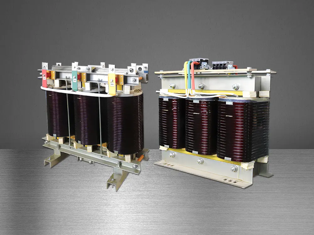 Three-Phase Isolation Transformer
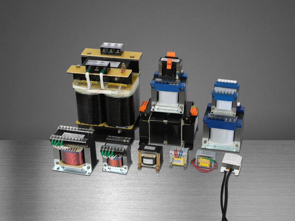 Control Transformer
 Medical IT Isolated Power System
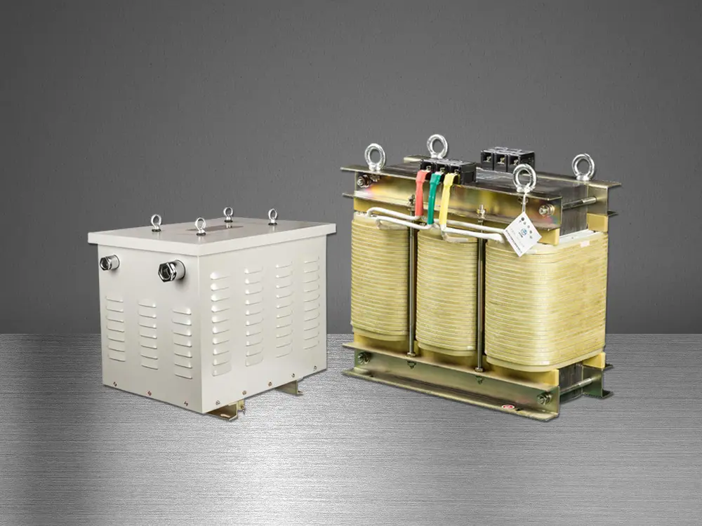 Marine Transformer
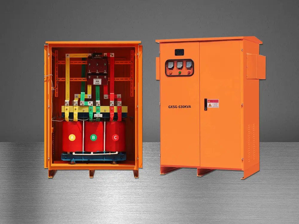 Tunnel Transformer
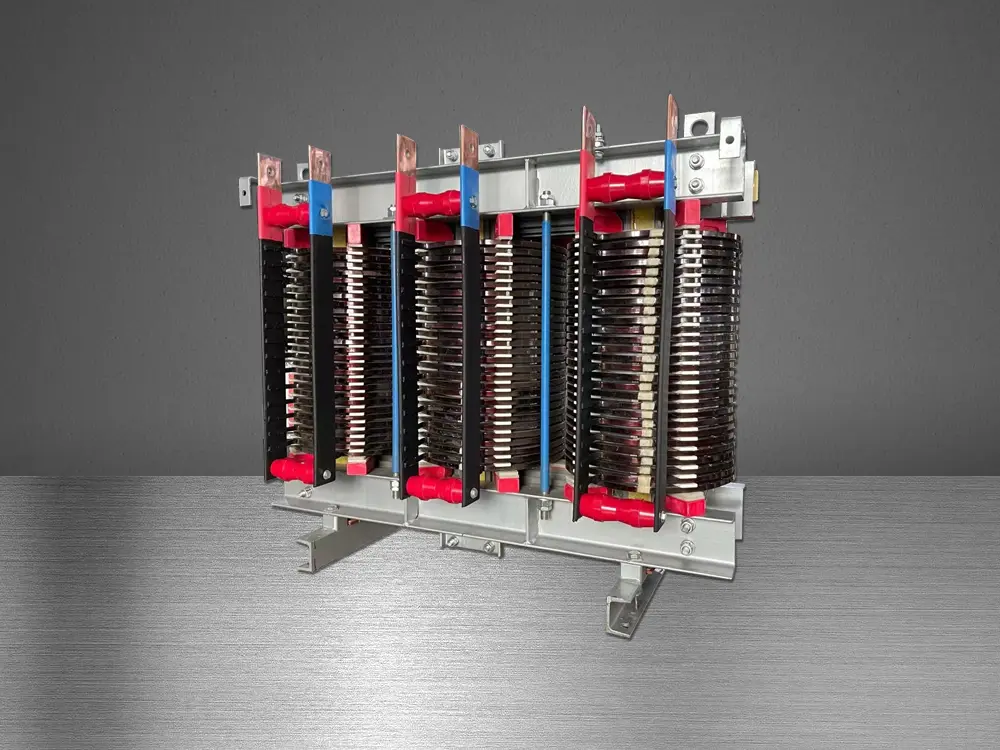 High Current Transformer
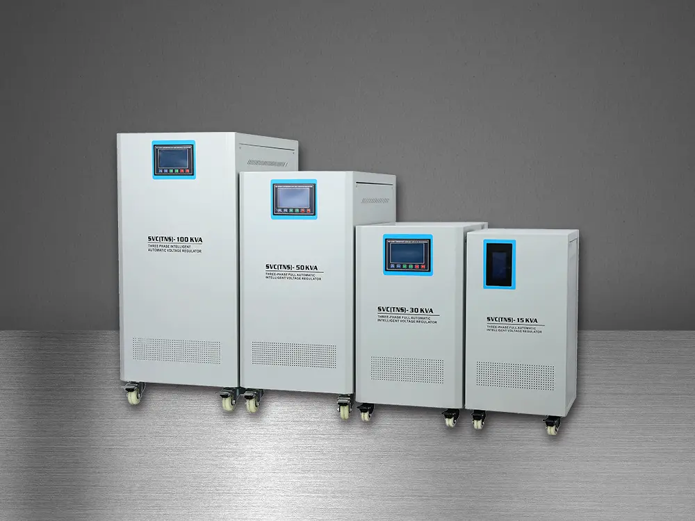 Automatic Voltage Regulator
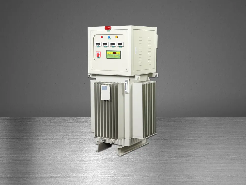 Oil Immersed Voltage Regulator